|
Upgrades The Freya Plus is a great Pre Amplifier, but like everything in life, not perfect. The top of the case, over the power supply, gets quite hot to the touch. I measured the temperature after 2 hours use at 20 deg C ambient, in free air on a table top. It was 46.4 deg over the centre of the PSU and 49.1 deg towards the rear. Around the tubes it was 43.2 deg C. These are case temperatures, the parts inside will be much hotter as there is no direct contact between parts and the case. I'm confident the design has been tested for reliability, but I would feel happier if I could get the temperature of the parts/case down slightly. The capacitors in the PSU are rated at only 85 deg C, I'm sure they will last longer in a cooler environment and give me many years of enjoyment. The first thing I did was fit some socket savers, these lift the tubes up and out of the case, this did reduce temperatures by a couple of degrees. These are the ones I fitted, sourced off ePay. 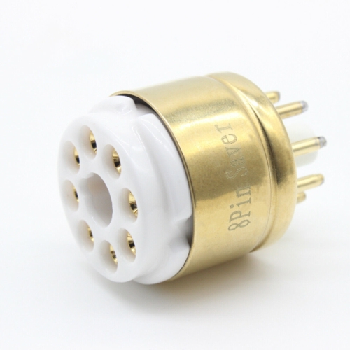 The next step involves a total strip down, so lets tackle getting into the case, removing the top cover and PCB. First remove the Tubes and any socket savers, if you installed them. Next, remove the volume knob - It just pulls off. Remove the Pots retaining nut and washer. The top cover now slides forward a small amount then up and clear. 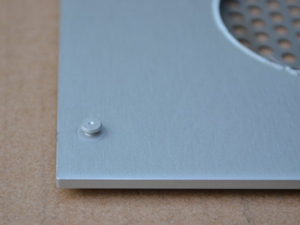 There are two Mushroom type studs on each short edge of the underside of the cover. 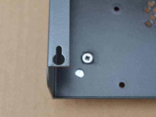 There are corresponding keyhole slots in the top face of the of the base part. Slide the top cover as far forward as it will go, this is only about 10mm, then back about 2 mm. If you don't move it back slightly, the mushroom head fastener will get stuck under the front edge of the keyhole slot. You should now be able to lift the cover off, just be careful you clear the shaft of the volume control, at the front face. The three push button caps will probably drop out of the front face as you do this, don't be alarmed. Tip: When re-assembling put masking tape over the front of the three push button holes. Fit the buttons from the rear and press against the masking tape. This will hold them in place while assembling. To remove the PCB, take out all of the screws on the base, these connect to the PCB stand offs. Next remove all of the screws on the rear panel, that hold the connectors, including the large ones into the power inlet socket. The PCB will now lift out as a complete assembly, no wires to disconnect. And this is what you have. 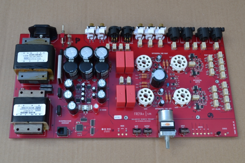 Now it's disassembled, the next and obvious step to improve cooling, is to increase the ventilation for the case. With the base stripped of parts, I drilled lots of 5mm dia holes (371) in the underside and installed some taller feet, to lift the unit up and allow air to get to the new vents. As a bonus, I think the taller feet look better, they also match my other gear. 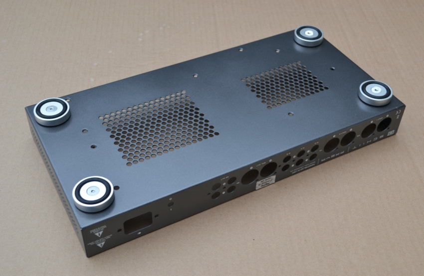 These are the feet I sourced on ePay, to replace the small rubber domes that were supplied. The PCB inside the Amp is on short 5mm stand offs, so there's not much clearance between protruding soldered wires under the PCB and the base plate. I used csk screws from the inside to hold the feet, thread locked them and covered the screw heads with Kapton tape. The feet are listed as 39x10mm, but the rubber ring gives a total height of 12mm with the units weight on them. 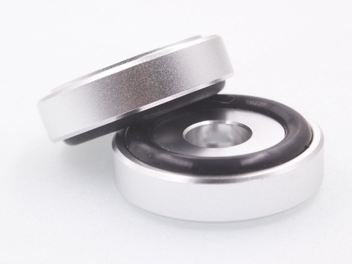 For the top face, I didn't fancy drilling holes as vents in the aluminium, I doubted I could do this accurately enough and it would end up looking shabby. Having said that, my efforts on the base almost looked machine punched. It was more about removing the anodized finish, which would tarnish and corrode over time. I painted the base after drilling the holes, to stop the steel rusting, but couldn't do that on the top cover. I found some smart Stainless Steel vent covers, that complimented the look of the hole pattern around the tubes and used those. 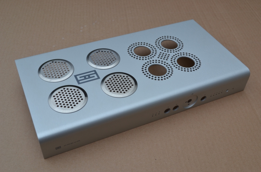 The four vent covers spaced quite nicely around the company logo. There's not much room between the top cover and the internal Transformers. I had to cut the protruding part of the vent covers down with a slitting disc, so they ended up flush with the inner face of the 3mm thick cover. I glued them in place, with high temperature Silicon Adhesive. The covers were sourced off ePay and are 65mm dia, with a 53mm dia protruding shoulder. I used a 53mm dia Carbide hole cutter to make the four holes. Volume Knob A minor irritation was the volume knob. The very small indentation which indicates the position of the knob, is almost invisible from most angles. I drilled it larger and deeper and filled it with red paint. 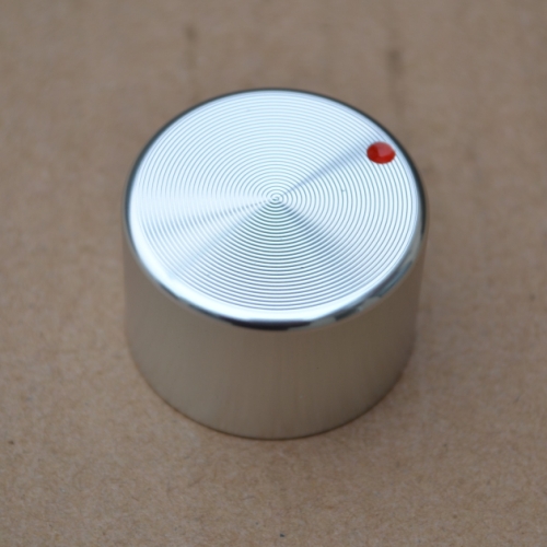 LED's All my equipment has Blue LED's, so while the unit was dismantled, I placed a small piece of transparent Blue, temperature resistant film, over each bank of White LED's on the PCB. I held the film in place with some Kapton tape. 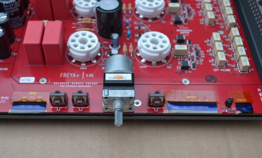 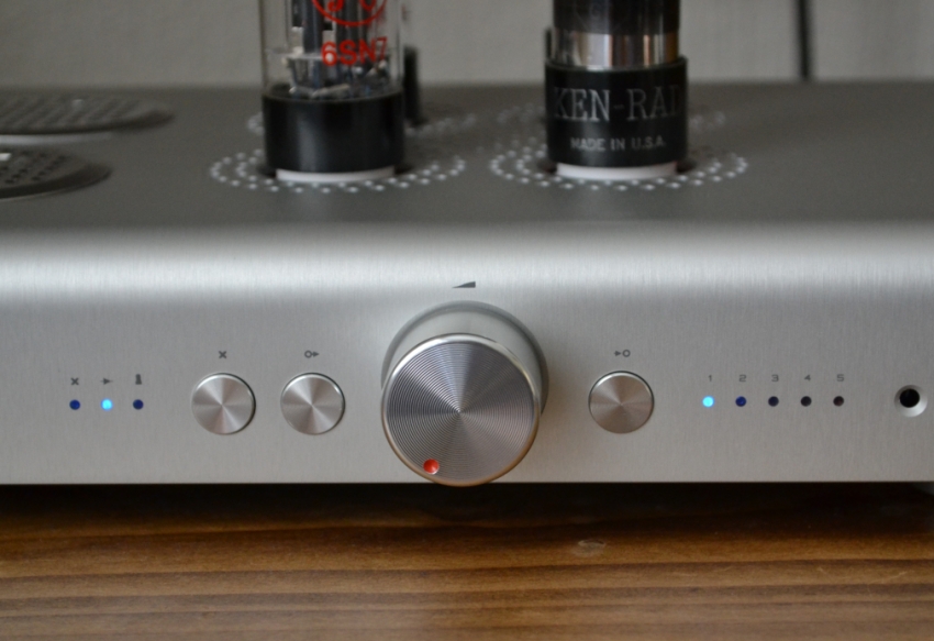 In the flesh, the Blue lights are a deeper colour, more of a Royal Blue than Turquoise. Stray Light Another minor irritation, was the stray orange light, from within the unit, that gets past the remote controls Infra Red sensor. This is visible from certain angles, through the sensors aperture on the front panel. I put a shield made from SRBP behind the sensor to block this stray light. 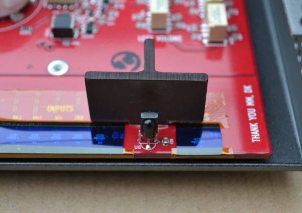 Output Capacitor Upgrade Several owners have recommended this, using the V-Cap ODAM capacitors (2.2uF 400Vdc). I know from other projects, that the stock Wima caps are easily bettered in terms of detail and transparency. So as a second bite of the upgrade Cherry I fitted these as well.  For best performance, these Caps need to be orientated so the outer foil is connected to the lowest impedance, in this case, the buffer tubes cathode connections. There are two cathode connections on each tube as they are dual triode tubes (Pin 3 and pin 6). The tracks for these can easily be seen on the top face of the PCB and dictate the cap orientation. The Caps themselves have a shorter lead at the outer foil end and the lettering on the label reads towards the outer foil connection. So if you fit them correctly, the labels should read as in my picture. These ODAM caps have metal bodies so care has to be taken that they do not to come into contact with any metal parts or PCB tracks. As a precaution I put two layers of self adhesive Kapton tape on the underside of each Cap and sheathed the Cap leads with PTFE tubing. I mounted the caps using silicon sealant to damp vibrations. The completed Upgrades 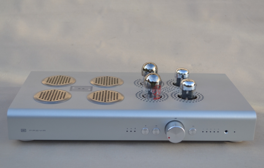 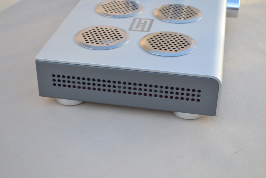 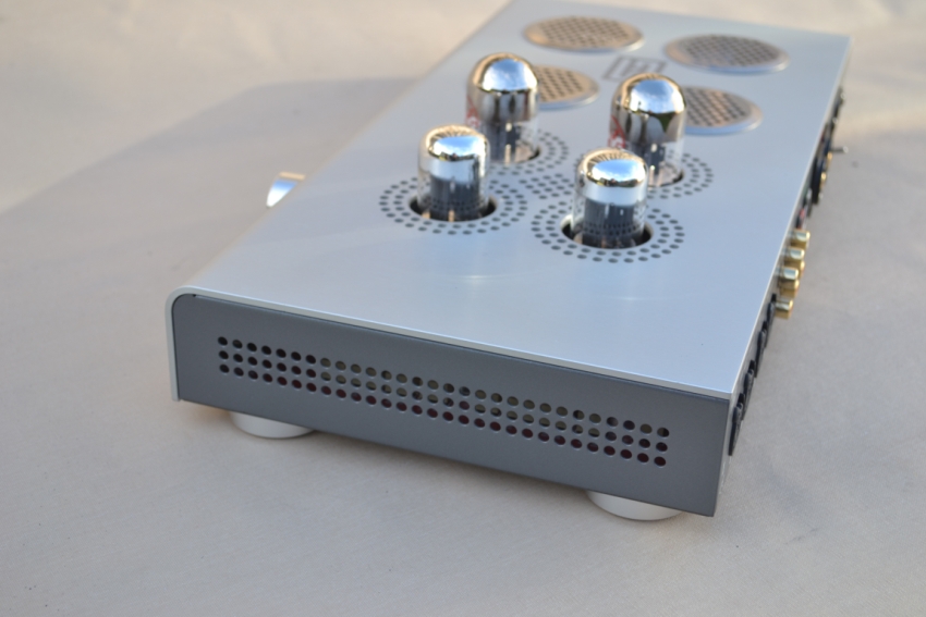 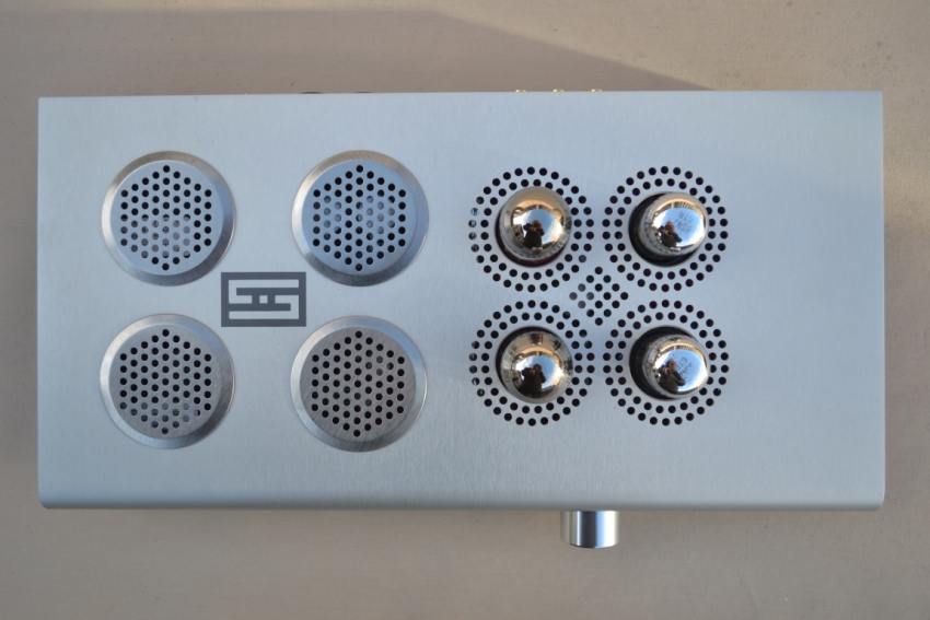 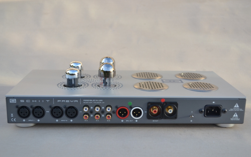 I replaced the two pairs of RCA output sockets with a single pair of high quality Neutrik RCA sockets (Red identifier). The pair of XLR sockets with the Green identifier, are fully balanced outputs. To sum up the things that I've done: Added Socket savers, to lift the Tubes out of the case (Cooling) Added additional vents to the top cover and base to further aid cooling Fitted taller feet, to match other gear and aid air flow to the new base vents Changed the colour of the LED function lamps to Blue (Match other gear) Prevented stray light from being visible through the remote controls sensor aperture Made the volume controls level indicator more visible Changed the Single ended output sockets Upgraded the output Capacitors. Post modification top cover temperatures Tested under the same conditions: 20 deg C ambient, in free space on a table top and after 2 hours playing. All deg C with stock temperatures in (brackets) LH side, in the middle, above PSU 39.9 (46.4) LH side at rear 40.2 (49.1) Around Tubes 35.2 (43.2) So there has been a reasonable reduction in case temperature. I'm presuming the parts are also running cooler, which was the reason for the modifications, in an attempt to increase the life span of this great product. Interestingly, I can feel the hot air rising out of the new vents with my hand above them. Especially the Left Rear, which has warmer air rising out of it, than if my hand is a similar distance over the tubes! Those Transformers get hot! Tube Rolling I acquired some NOS Ken-Rad VT231 Black Glass for the Gain positions on the Right. These are a WWII military grade 6SN7, mine were made in 1943 for the US Signal Corp as indicated on their cartons. These have a reputation as King of bass when it comes to 6SN7's. For the Output Buffer, I changed to NOS (1950's) GE 6SN7GTA. This combination works extremely well, giving crisp detailed highs, smooth mids and a killer bottom end, grungy guitars have a real raspy edge to them. The Capacitor upgrade improves transparency and gives a cleaner and clearer view into the detail of the music, the top end is now smoother, overall I think this is a worthwhile and quite a noticeable improvement. |
 |
 |