Active electronic X-Over (eXO) I
tried running the whole 3-Way set up using DSP, trying both Hypex and Minidsp products, whilst they sounded good
with digital sources, my analogue TT/Phono stage, took a big step
backwards. The ADC's used are just not good enough, so I stuck to a
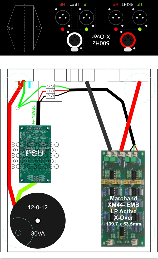
purely analogue, op amp approach for the LP active circuit. This is the layout I started with.
 I
tried several op amp based active X-Overs, including those from KMTech, Rod
Elliott (ESP) and Marchand Electronics. All three are based on a similar
circuit and not surprisingly have similar, good quality sound.
I finally settled on the Marchand XM44EMB (Embeded) which is a small two channel unit, meant for installation inside amplifier or loudspeaker housings. It has some good features, including balanced or single ended inputs and adjustable output levels. In particular, it has easily swappable plug in X-Over and Bass boost modules (Linkwitz Transform) available, made to your requirements by Marchand. There's also a down-loadable calculator for these modules and unpopulated PCB's are available, so you can experiment with different slopes and X-Over points on a DIY basis. P05C PSU I used Rod Elliott's Project P05C Power supply, a simple and very quite supply, intended for his Pre Amp Project. Link to Rod Elliott's site and projects (Elliott Sound Products): https://sound-au.com/ Most op amps operate over a wide voltage range, from around +/- 5Vdc to +/- 15Vdc or more. The AD8066 however, which is one I wanted to try, has an absolute max voltage requirement of +/- 12Vdc. Some of the discrete op amps have reduced performance below +/- 10Vdc. So I settled on a regulated +/- 11.2Vdc as a suitable compromise. I closely matched the voltage setting resistors and also the regulators themselves. The measured output from this supply, with mains at 239Vac, used in circuit and under load, is +11.228Vdc and -11.213Vdc. This is very close matching of the rails. 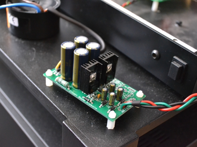 I used Panasonic FC Caps and Takman 1% Metal Film resistors. Don't be tempted to use an inferior Chinese PSU, this one works well, producing a very Black background. Marchand XM44EMB Electronic X-Over (eXO) 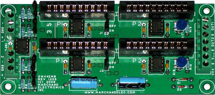 The Troels Grevesen HP passive x-over I used, for the midrange driver, is second order, -3dB at 500Hz. With the midrange drivers natural roll off, these slopes combine to give an acoustic response which is an almost perfect LR4 curve, with a -6dB point of 451Hz. The Scanspeak bass driver has a flat response either side of this frequency, so I aimed for an LR4 electronic slope with -6dB at 451 Hz. Using stock resistor and capacitor values for the filter, the closest I could get was LR4 464Hz, which is close enough (22nF and 11kohm used). There is no reference to any limits, for the value of these filter parts on the Marchand website. Rod Elliott, being more DIY orientated gives advice for the filter parts as follows:
"In
general, avoid capacitors less than 2.2nF or greater than 470nF. As
noted above, low values become susceptible to stray capacitance and
high values may cause excessive opamp loading. I kept this in mind when choosing the values for the Marchand. From the many crossover variations I tried, this gave the best results, with good phase integration and a smooth transition. I experimented with one of Rod Elliott's P87B dual channel Balanced Transmitter boards. This converts the single ended outputs of the Marchand X-Over to balanced, by creating the additional inverted signals. While it gave a nice +6dB boost to the output level of the LF (as balanced), I felt its inclusion, with the extra parts, degraded the sound slightly. Likewise, using the Bass Boost modules gave an f3 of around 20Hz, but added even more complication to the circuit. In both situations I found simpler sound better, so I removed both features and kept to a simple Single Ended in/out and just a LP filter set at 464Hz. So after all my experimenting I had what I considered to be the best solution using this board. If you look at the picture of the Marchand board above, you can see there are numerous terminal blocks, jumper bars and sockets, providing many locations where the signal could be degraded. I removed all of these and soldered the parts directly to the board. The stock design uses basic 1/4w 1% Metal Film resistors and Polyprop Caps. I used 1/2w Takman 1% metal film resistors and Vishay MKP1837 1% Polypropylene caps, which were further graded and matched. I also used Panasonic FM electrolytics on the power rails and Charcroft 1% Silver Mica Caps on the input. The monolithic (Chip) op amps supplied with the board, are dual channel, unity gain compatible, OPA2134. I have always found these to sound dull in active crossovers and lacking transparency. After trying many and I mean many, chip based and discrete op amp combinations, my final choice was a Sonic Imagery 994Enh-Ticha discrete op amp for the input buffer and a pair of Muses 01 chip op amps for the filter modules. This combination sounds detailed, dynamic, transparent and with just the right amount of colour to render instruments and voices in a natural way. |
 |
 |